

What do orthopedic angles and lines actually tell you?
Orthopedic angles and lines show bone alignment, joint shape, and the place of key landmarks. They help turn an image into a number that can be checked. They do not turn a single number into a clinical answer. A sharp-looking line on a poor view is still a poor reading. This guide covers common examples from the spine, foot, hip, knee, and wrist. Start with the body part and the question at hand. Then confirm the view, the landmarks, and the normal range. A child’s hip is not a small adult hip. A standing foot film is not the same as every unloaded image. The useful habit is simple: name what you measured before judging whether it is normal. Numbers support a reasoned reading. They cannot replace the history, exam, or the rest of the scan.
Cobb angle: measure the curve, not the whole diagnosis
The Cobb angle measures the size of a spinal curve on a defined X-ray view. For a scoliosis curve, use the upper endplate of the upper end vertebra and the lower endplate of the lower end vertebra. The angle can be found from those lines or their perpendiculars. The Scoliosis Research Society glossary defines idiopathic scoliosis on X-rays as a lateral curve of at least 10° with rotation and no known cause. That threshold is not a surgery rule. Age, growth, symptoms, and change over time still matter. Among orthopedic angles and lines, this is a common source of false certainty. A report should name the end vertebrae so a later film can be compared fairly. If the chosen levels or body pose differ, pause before calling a small change true progression. Measure the same way. Read in context.
Sacral slope and lumbar lordosis: state the reference lines
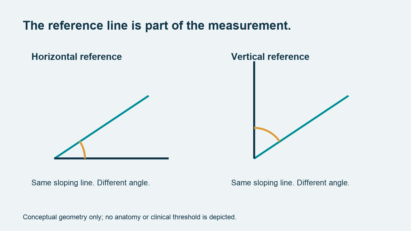
Sacral slope and sacral inclination use distinct landmarks. In the source article, sacral slope is the angle between the top endplate of S1 and a horizontal line on a standing lateral image. Sacral inclination uses the back border of S1 and a vertical guide. The names sound close. The readings are not the same. The source also illustrates lumbar lordosis using L1 and L5 endplates; other methods use distinct end levels. Those values should not be mixed without reason. Orthopedic angles and lines lose meaning when their definitions vanish from the report. Do not turn an average sacral slope into a fixed target, or label a spine unstable from that value alone. Record the posture, end levels, and method. Then assess the curve in relation to the pelvis and the person’s signs and symptoms.
Böhler and Gissane angles: different questions at the heel
Böhler’s angle helps assess the shape and height of the calcaneus on a lateral view. Its lines use the high points of the anterior process, posterior joint facet, and heel tuberosity. AO Surgery Reference lists 25–40° as a normal range. A reduced angle can reflect collapse after a fracture. It is one clue within the full injury review. Gissane’s angle uses the intersecting slopes of the upper calcaneal surface and shows a distinct part of its shape. The supplied article lists 120–145° for that method. Orthopedic angles and lines should be tied to the exact landmarks used, especially when published ranges differ. An apparently normal heel angle does not settle every fracture question. Look at the joint surface, heel width, alignment, and other views. A number that looks reassuring must still fit the injury.
Hallux valgus: keep HVA and IMA separate
The hallux valgus angle measures the first metatarsal against the proximal phalanx of the great toe. The first–second intermetatarsal angle measures the axes of the first two metatarsals. One shows toe deviation; the other shows the spread between those bones. The supplied guide gives HVA below 15° and IMA below 9° as common normal values. State the view and whether the foot bears weight. Do not compare films made in distinct poses as though nothing changed. These orthopedic angles and lines can grade shape, but they cannot choose an operation by themselves. Pain, shoe problems, joint state, and the wider foot pattern remain part of the review. A dramatic X-ray is not the same as a severe daily problem. Equally, a modest number does not dismiss a patient’s symptoms. Keep the image and the person in the same conversation.
Hip coverage: what does the lateral center-edge angle mean?
The lateral center-edge angle shows the side coverage of the femoral head. On an AP pelvis view, it relates a vertical line through the head center to a line toward the lateral acetabular edge. The POSNA guide to adolescent acetabular dysplasia gives traditional categories: below 20° is dysplastic, 20–25° is borderline, and above 25° means normal lateral coverage within that scheme. POSNA also stresses that the angle alone cannot show the whole disorder. That is the point worth remembering. Orthopedic angles and lines assess parts of a 3D joint. They do not capture it all. In infants and young children, the acetabular index instead uses Hilgenreiner’s line and the acetabular roof. Its expected value changes with age. Never apply an adult coverage threshold to a child’s growing hip without the proper age-specific method.
Knee alignment: an axis choice changes the answer
A knee angle is incomplete until its axis and viewing plane are named. A shaft-based anatomical axis and a mechanical axis answer distinct questions. The supplied article includes coronal knee angles, the posterior proximal tibial angle, and the Q angle. Treat them as separate measures. PPTA relates the tibial shaft axis to the proximal joint line on a lateral image; the source gives about 81° ± 3° for its stated method. A larger value in that convention means less posterior slope. The Q angle uses the anterior superior iliac spine, patellar center, and tibial tubercle. It is not the same as an X-ray measure of bone alignment. With orthopedic angles and lines, labels such as “knee angle” are too vague to audit. Record the landmarks, limb pose, and method before judging a stated change.
Distal radius: distinguish radial inclination from palmar tilt
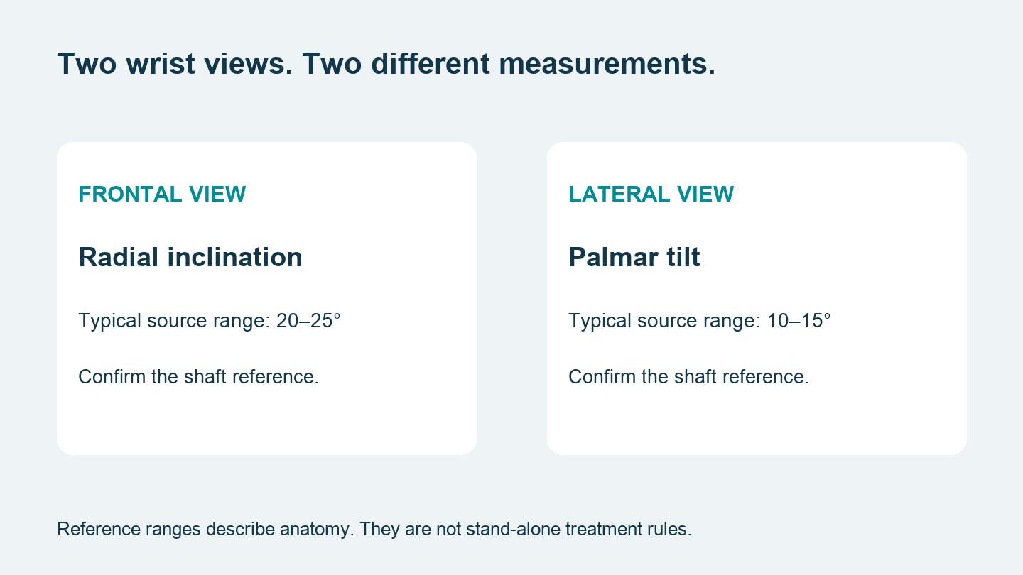
Radial inclination is checked on a frontal wrist view; palmar tilt is checked on a lateral view. For inclination, compare the distal radial joint line with a line perpendicular to the radial shaft. For tilt, compare the line joining the palmar and dorsal articular rims with a perpendicular to the shaft. The source gives usual values of 20–25° and 10–15°, respectively. These show usual bone shape, not fixed treatment targets. AO’s distal forearm imaging guide shows why standard and extra views matter when judging the joint and hardware. Orthopedic angles and lines can help show a distal radius fracture, but tilt alone misses shortening, joint steps, and other injury. Ask whether the image is a true lateral before trusting a precise-looking result. A wrong projection can make the right ruler tell the wrong story.
Carpal angles: a warning sign is not an automatic operation
The scapholunate angle compares the long axes of the scaphoid and lunate on a lateral wrist image. The supplied article lists a common normal range of 30–60°. AO’s scapholunate repair guidance checks lateral alignment with a neutral lunate and an angle below 60°. That is a guide used in surgery, not proof that every value above it requires repair. Radiolunate and capitolunate angles add detail about the direction of carpal tilt. The image, symptoms, and ligament review must agree. Finish with this short checklsit when reading orthopedic angles and lines:
- View: is the projection suitable?
- Method: are the axes and landmarks stated?
- Context: does the finding match the patient?
If any answer is missing, the reading needs more work. A precise number deserves a clear explanation. It should never become a shortcut around clinical judgement.